Project Introduction
The COVID-19 pandemic forced many people to work from home. During this time, I thought it would be fun to create some potassium nitrate (KNO3) and sucrose (C12H22O11) propellant, abbreviated as KNSU. I started this project by diving into solid rocket motor theory, which can conveniently be found on Richard Nakka’s webpage (http://www.nakka-rocketry.net/articles/nakka_theory_pages.pdf). Nakka has an excel spreadsheet on his website which assists with KNSU propellant design. Using knowledge obtained from theory in conjunction with the spreadsheet, I was able to create a valid design for small scale propulsion test with a chamber pressure of 800 psi.
Propellant Fabrication
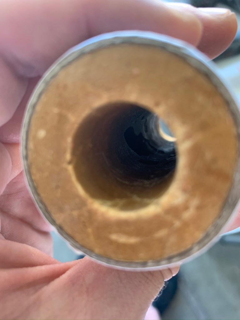
Due to lack of machining capabilities and a strong desire to meet the design constraints, the molds for the propellant were made from 3D printed PLA. The main con to using PLA over smooth metal for casting materials is that the propellant tends to get very stuck to the coring tool. Drilling was required to remove the tool everytime, which is not ideal as the grain can be damaged. Periodically, cavities appeared within the grain, likely due to improper packing, vibrations from drilling, and lack of constant pressure. The method used to prepare and cook the propellant is shown below in the table.
Design and Analysis
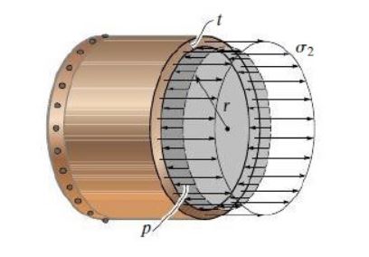
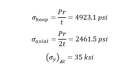
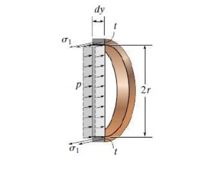
Once the grain size and nozzle geometry had been determined, it was time to develop a thrust chamber capable of withstanding the internal pressure and temperature produced in the combustion process. 6061-T6 Aluminum was selected for its common use in this application. Typically, a phenolic liner is employed to limit heat transfer to the combustion chamber walls, however, a cardboard liner was chosen instead due to cost and time constraints. Axial and hoop stresses were evaluated to determine at what pressures the material would yield.
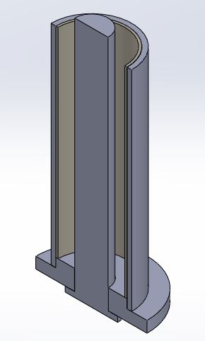
Once it was determined that aluminum would be a suitable motor casing, it was time to create a bulkhead and nozzle. The excel spreadsheet automatically determines the necessary dimenions for optimal nozzle expansion. Using these values, the nozzle can be designed.
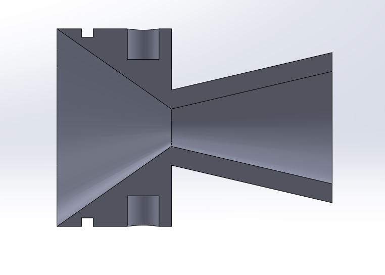
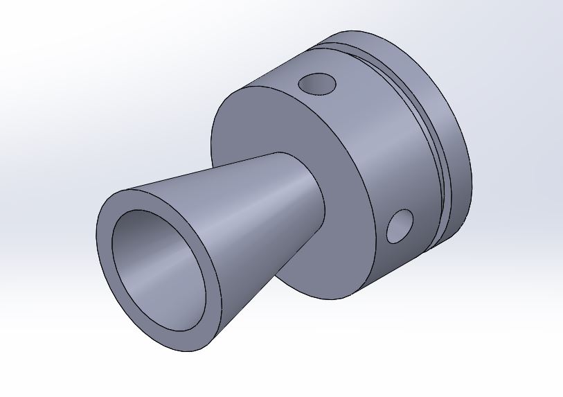
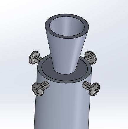
An o-ring groove was added so that a silicone o-ring could prevent gases from escaping through any potential voids between the nozzle and motor casing. Because I lacked access to a lathe, neither external nor internal threads could be created which would hold the nozzle inside the casing. Instead, I opted for dowel pin holes. Four holes were drilled through the motor casing which aligned with the holes shown in the nozzle. Stainless steel screws were inserted to act as dowel pins, holding the nozzle in place. Shear and bearing stress calculations were performed to ensure the neither the bolt nor aluminum underwent yielding.
The nozzle was made via 3D printed PLA. My roommate had previously tested a PLA nozzle successfully using KNSB propellant. Sorbital has slightly lower chamber pressures, so I opted to try this method. A video of my friends static fire is shown below.
With the nozzle complete, the last piece of the combustion chamber was the bulkhead. Attaching and sealing the bulkhead became difficult due to the lack of a lathe. I was able to acquire an aluminum “plug” to fill out the bottom, but neither threads nor an o-ring groove could be machined. Both steel reinforced JB Weld and ExtremeHeat JB Weld were employed to resolve this issue. The ExtremeHeat JB Weld was placed internally at the bottom of the motor casing. It was rated up to 1300°C, which was about 200°C lower than the combustion temperatures. This was meant to act as an ablative barrier for the steel reinforced JB Weld which was applied externally to attach the aluminum plug to the casing. The tensile strength was rated up to 3900 psi, making it strong enough to withstand the axial stress. The main uncertainly was the adhesive strength. The value was not listed on the data sheet, but a similar product was rated up to 2400 psi. Because of this, it was expected that the JB Weld would yield for the 800 psi KNSU propellant. A 300 psi nozzle was designed to lower the expected force output. A bolt was also impregnated through the wall into the aluminum plug to prevent it from being pushed out.
Last came the test stand and electronics. The test stand was designed in SolidWorks and printed from PLA. My friend, Nick Chai (https://www.linkedin.com/in/nicholas-chai-438577178/) handled the electronics for this project. The primary electronics consisted of an arduino nano, a relay, and an 80 kg load cell. The final product is shown below.
Testing and Results
We began by testing a spare H-135 motor we had to evaluate how efficient the load cell was at recording data. Once this was complete, we proceeded to test the first grain with a 300 psi chamber pressure. The ignition sequence succeeded, but early on the nozzle melted and blew off. Some data was obtained prior to this, but it is uncertain how accurate the data was. From this project, I learned a great deal about solid rocket motor theory and gained invaluable design and fabrication experience. In the future, I would like to reattempt this using machined pieces instead. The likelihood of more substantial success would be significantly higher.
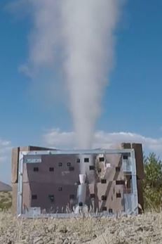
300 psi 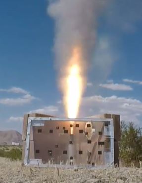
H-135 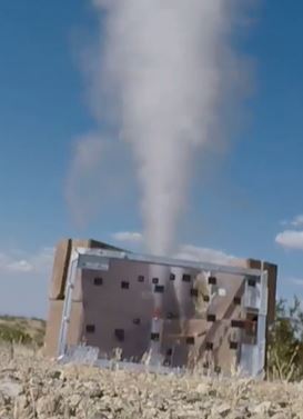
800 psi