Project Introduction
The goal of this project was to develop a multi-stage rocket designed to reach the highest altitude possible A.G.L. while being limited by a 640 Ns total impulse cap. A minimum of two stages will be required for entry. In addition to manufacturing and launching a multi-stage rocket, three reports consisting of a design report, technical manufacturing report, and a post-flight analysis report will be required.
Preliminary Design
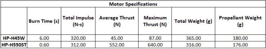
For this project, I became the lead design and manufacturing engineer. As usual, I started by iterating through several designs in a software called RockSim. This was our first year making any sort of multi-stage rocket, so to reduce complexity we opted for a two-stage design. In order to reach higher altitudes with the provided motor constraints, the diameter was kept low. This is because drag force significantly increases as the diameter of the rocket increases. Two 38 mm H motors were selected, allowing us to maintain a small diameter while still giving us some space to work within the rocket. The table below provides the specs for the motors we utilized.
At the amateur rocketry level, many rocketeers use a motor staging system consisting of a booster motor followed by a normal motor. As soon as the booster motor completes its burn, it lights the next successive motor and causes a stage separation. While simple, this method has considerable drawbacks if you’re trying to reach the highest altitude possible. By immediately firing the next successive motor, you’re not effectively reaching the max height you could reach on that single motor. Instead, it is more effective to wait some time before firing the upper stage motor, which is what we opted to do. Various delay times were simulated on the upper motor in RockSim until we found the max possible delay before apogee. To account for error, this max time value was reduced by 2 seconds, providing some error margin.
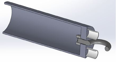
To detach the upper stage, we will be relying on the exhaust pressures generated from firing the upper motor to cause separation. Excessive paper wadding will be placed in the lower stage to prevent the parachute and electronics from getting burnt. In addition to this, the motor will also be used as the coupler connected the upper and lower stage.
In early designs, simulations showed an expected apogee of 14,500 – 15,000 ft, but as the avionics and manufacturing techniques evolved, so did the weight of the rocket, ultimately causing the predicted apogee to drop to 11,500 ft.
Analysis
To continually improve my analysis capabilities, I always perform FEA on critical parts such as the fins and nose cone to increase the level of confidence in the design. In particular, our SEDS chapter likes to 3D print components due to ease of manufacturing, but the likelihood of structural failure also rises (depends on material selection and other 3D printing factors). As the rocket approaches Mach 1, components start heating up quickly. Standard 3D printing materials (PLA in our case) melt around 200C. As such, analysis is performed to validate designs.
The images below show the nosecone CFD and FEA results. CFD is a useful tool in this application because the pressure the nosecone undergoes can be recorded and exported to FEA. Material properties for PLA can be hard to find due to its viscoelastic nature, however, the SolidWorks database conveniently already has ABS (slightly stronger 3D print filament) in its library. This is used a substitute with reasonable accuracy. The CFD results show that the tip of the nosecone experiences the highest pressure loading, which is expected. Despite this, the FEA confirms that the nose cone design does not come close to the yield strength of the material. Looking back, the mesh sizing could have been dramatically improved.


The second, more critical part are the fins. In my experience, structural failures most often occur here, resulting in shredding or non-optimal trajectories (cool but scary horizontal rockets). On larger rockets, bracketing or slotting is used to minimize the likelihood of failure occurring, but neither can be used on a minimum O.D. rocket. On small rockets like these, we use epoxy. Adhesion simulations can be difficult to perform, so instead, the same techniques used on the nosecone are implemented, shown above. With this data, we can determine if the expected pressure loading exceeds the epoxies limitations, which is did not. Our fins are typically laser cut from 1/4″ plywood, which is what was modeled. The simulations showed that the front tip of the leading edge experienced the most pressure, so additionally epoxy was added here. Lastly, we were able to validate that yielding would not occur.
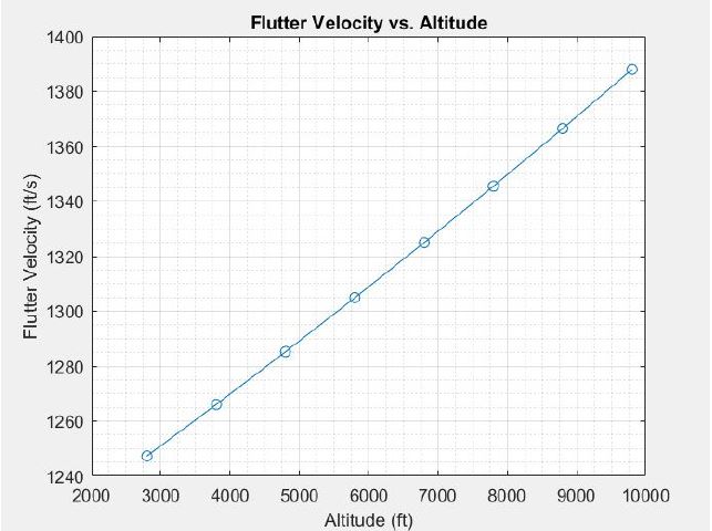
In addition to analyzing stress, flutter velocity is also inspected vs. altitude using a MATLAB script. The max velocity of our rocket is expected to occur around 8,000 ft. From the flutter velocity graph, a velocity of approximately 1350 ft/s is required, which exceeds the projected max velocity of 1000 ft/s for our rocket.
Manufacturing
Several parts, including the nosecone, avionics bay, and upper stage coupler, were 3D printed from PLA. The nose cone utilized 100% infill, but was hollow and only had four walls. The coupler was similar, but had a 30% infill in the larger base region to reduce weight. Lastly, the avionics bay was around 5-10% infill which dramatically cut weight, ultimately totaling 30 grams.

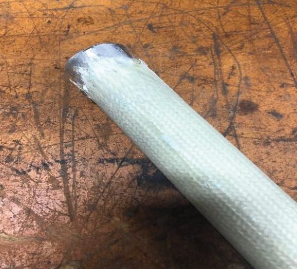
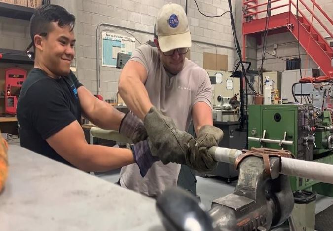
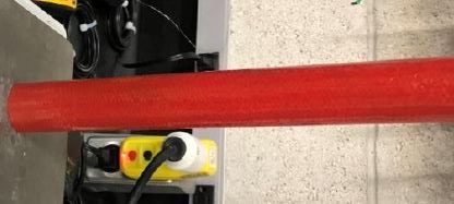
For this project, we decided to make our first attempt at composites manufacturing of our body tubes. This was done to reduce cost, weight, and diversify our skill sets. Similar to the SA Cup, my teammate Nick Chai and I led the composites manufacturing. We purchased [+45/-45] PW fiberglass sleeves from Soller Composites. A long aluminum round found in our machine shop was found, sanded, polished, and used as the internal mold for the composite sleeves. Through trial and error, we eventually reached a decent method of manufacturing, but it could still be improved in the future. A detailed description of the manufacturing process can be found in the report.
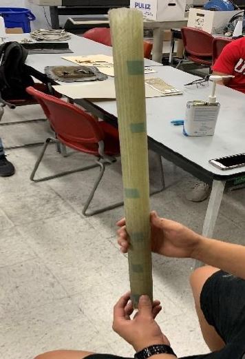
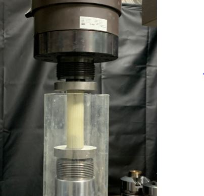
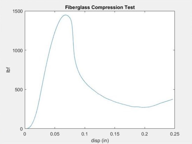
Ultimately, only one ply was used for the body of the rocket, a very risky decision. This was done to reduce the weight as much as possible. To validate the strength of the manufactured composite tubes, a compression test on a MTS was utilized to test the compression and buckling strength. From these test (shown below), a max value of 1,448 lbf was achieved at a deformation of 0.068 axially. The measured value far exceeded the expected drag force, indicating the feasibility of our tube.

The next step was to reduce the skin fraction drag imposed by the rough composite surface. To do this, three layers of primer were applied, followed by a small amount of epoxy. In addition to smoothing out the surface, the epoxy worked to fill any potential voids in the matrix. The final tubes ended up weighing about half the commercial options.
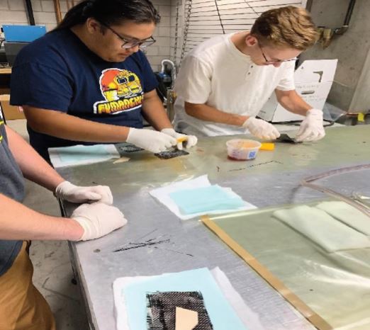
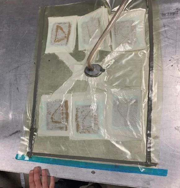
Lastly, the fins were also manufactured from composite materials. First, 1/4″ plywood is laser cut into prescribed shapes. Next, the edges are beveled using a belt sander. Once this is complete, one ply of a [0/90] carbon fiber (CF) weave is applied to increase the strength. Due to the size of the fins, we opted to use the “sandwich” method, in which one sheet of CF is applied to each side instead of wrapping the fiber over the leading edge. For our process, we directly apply the epoxy resin to our CF thoroughly with brushes, effectively “wetting” the surface. The fin is then placed in between two sheets of wetted CF. Teflon breather and cotton is applied to both sides before being placed into a vacuum bag overnight. As a side note, we also used this opportunity to teach new members how to make CF composite with internal molds.

Avionics
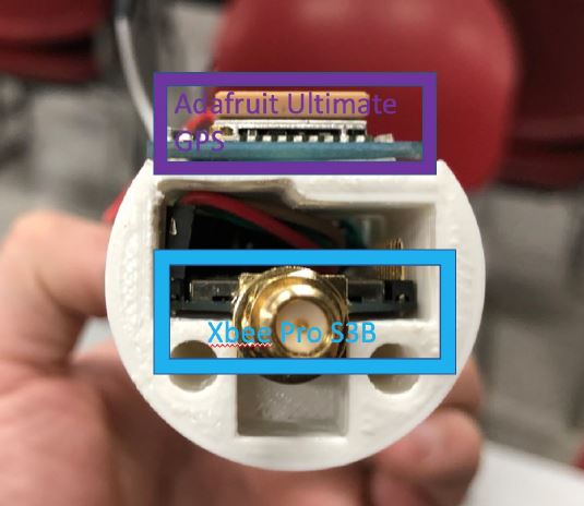
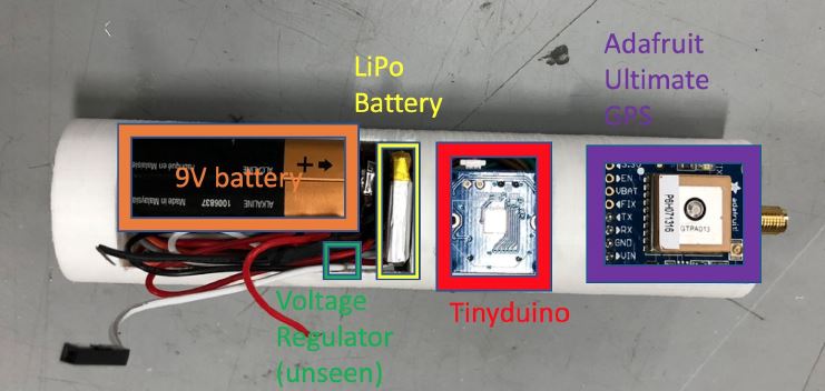
The avionics for this project was led by several other members. Two separate avionics bays were required for this project. The first one, located in the uppermost stage, contained the following electronics:
- APRA Altimeter
- Stratologger
- Xbee Pro
- Lipo Battery
- Adafruit Ultimate GPS
- Tinyduino
- Timer
- 9V Battery
A custom avionics sled was designed to hold all electronics securely in place, shown below. The second system located in the lower stage also had a 9V, microcontroller, GPS, and a transmitter. A smaller avionics sled was also printed to hold components in place.


Pre-Flight Testing
The final check list requires testing stage separation, telemetry connection, parachute deployment, and shock force validation. Using an in-house excel sheet, the theoretical mass of black powder can be determined quickly without needing to perform extensive trial and error testing. Shown below is a video of our first test.
Using information generated from the ejection charge calculator, we can also determine the anticipated shock force using an MATLAB script courtesy of Cambridge Rocketry. This allows us to select the properly sized shock cord.

Launch
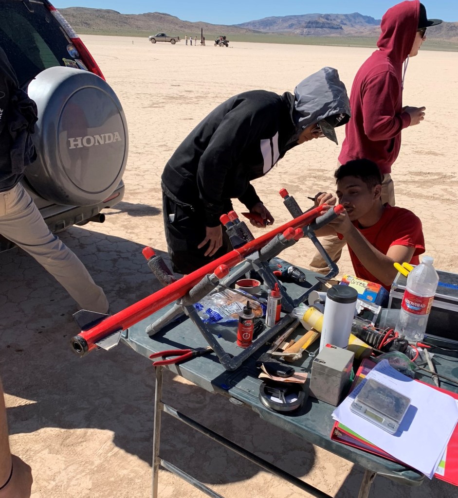
On launch day, our stratologger began malfunctioning and incorrectly firing the e-charge when inserted into the tube (despite having numerous pressure taps). At the time, we did not have a backup, so we could not launch the rocket. Results will be posted at a later date after launch has occurred. Until then, enjoy this picture of our team members working on the rocket at the launch site!
Final Report PDF