
Project Introduction
The Spaceport America Cup is the world’s largest competitive rocketry competition. Each year, student teams assemble in Spaceport America, NM to launch rockets in several different categories. In 2019, I competed for the first time with SEDS UNLV in the 10,000 ft commercial-off-the-shelf (COTS) motor class. Additionally, a payload of 8.8 lbs minimum was required.
Design and Analysis
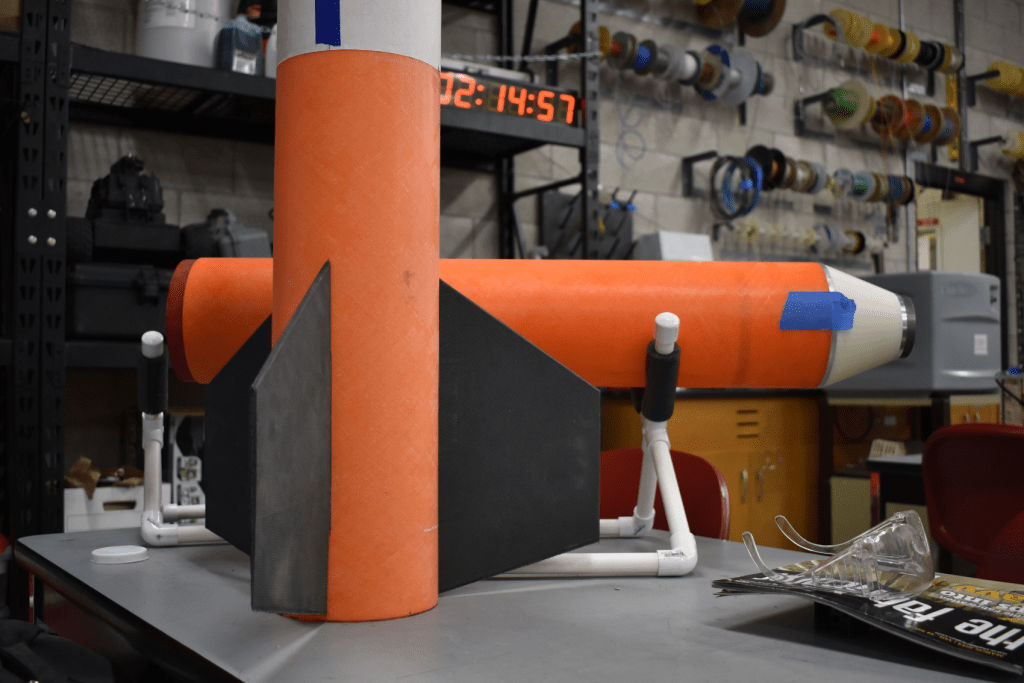
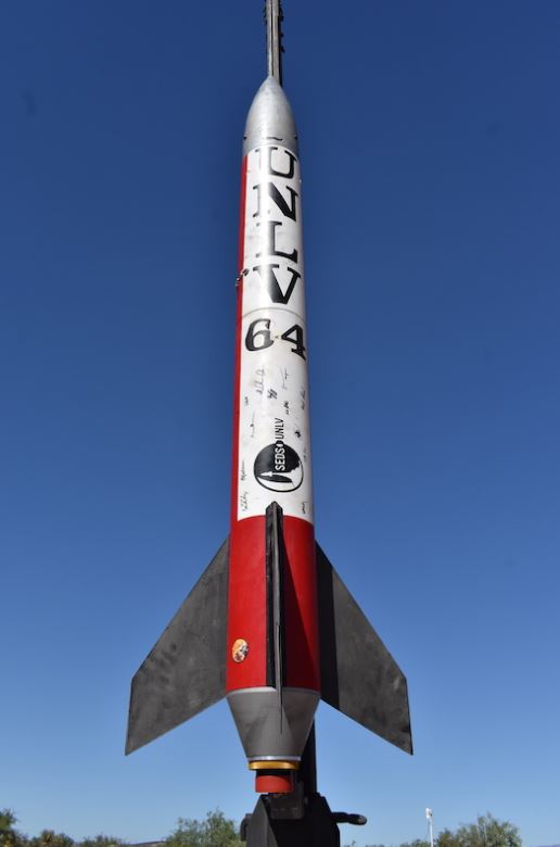
I took the role of lead propulsion and airframe designer. This role largely consisted of designing the rocket, running flight and structural simulations, and fabrication of rocket components. For this competition, I utilized a paid software called RockSim to assist in the design of the rocket. The final designed produced a 6.15 ft tall, 6.2 in diameter rocket named “The Loveship.”
The competition required a stability margin of 1.5 – 2.0, which we successfully acheived, producing a value of 1.72. As the electronics design evolved, modifications in weight were offset using weights in the nosecone. Once a suitable design had been chosen, the parts were modeled in SolidWorks to get a feel for sizing constraints and analysis.
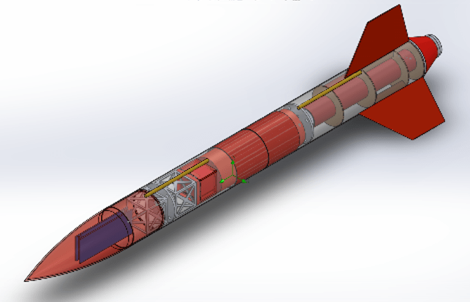
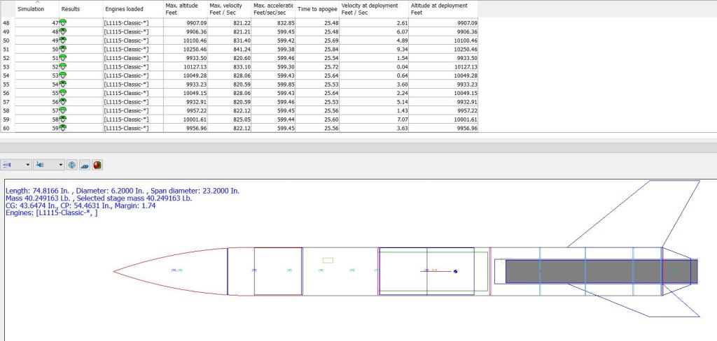
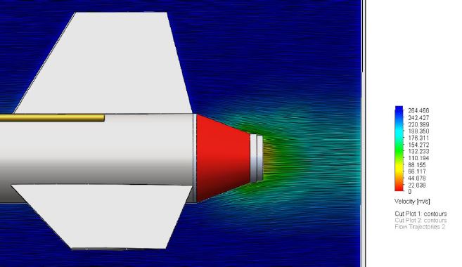
The decision to add a boattail came after we struggled to reach 10,000 ft on a level 2 L1115 motor. At that time, we did not have a level 3 certified member and were unable to purchase a level 3 motor. After much experimentation in RockSim, a suitable boattail designed was acheived, which increased our expected altitude by nearly 500 ft. It was decided that the boattail would be 3D printed out of ABS, which presented a slight design challenge. The motor casing typically sits on the boattail while firing. To prevent the ABS from being crushed, I machined a 6061-T6 aluminum tube to fit inside the inner diameter of the ABS boattail, which the motor casing could sit on. A thrust plate, also made of 6061-T6 Aluminum, was machined from a solid plate to provide a resting place for the aluminum tube. In addition to providing a base for the aluminum tube, the thrust plate effectively transfers the loading off of internally epoxied centering rings to the exterior fiberglass tubing. A fiberglass motor mount was purchased from Madcow Rocketry and centered inside the lower stage with laser cut plywood centering rings. Rocket-grade epoxy was used to adhere the centering rings to the inner diameter (I.D.) of lower stage tubing.
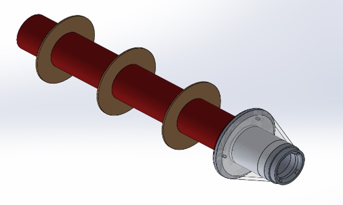

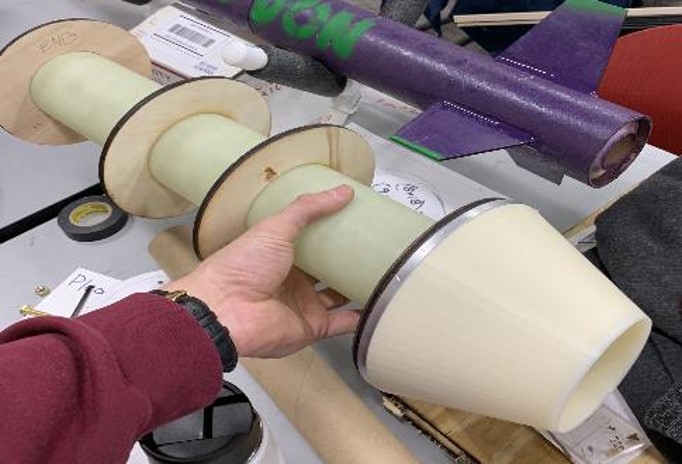
Further modifications were made to the thrust plate to help with mass reduction. To ensure the thrust plate and aluminum tube were able to withstand the load, both hand calculations and finite element analysis (FEA) were performed. SolidWorks provides both the capability to perform FEA as well as computational fluid dynamics (CFD) with reasonable accuracy. In addition to verifying the strength of this design, CFD was performed on the boattail to observe the effects with and without it.

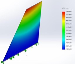
Following the completion of the lower propulsion system, fin fabrication came next. Being that it was our first year with a large rocket, we encountered some unique design hurdles that needed to be overcome. For this project, we decided to enhance our fin fabrication techniques, which led us to the realm of composites. Because computer numerical control machines (CNC) were largely unavailable to make make molds, my teammate Nick Chai and I opted to wrap carbon fiber (CF) composite material over 3D printed ABS fins, something that had never been performed before at our school. The fins themselves utilized a symmetric airfoil design and included a rectangular piece on the bottom used for slotting the fin inside the body. Internal cylindrical passages were printed within the fin and rectangular piece which carbon rods were inserted into. This was used to connect the two pieces. Two plies of [0/90] CF were applied to the exterior of the 3D printed fins. Resin was manually measured and applied to each layer of the CF. We chose to use the vacuum bag technique to remove excess resin from the layup.

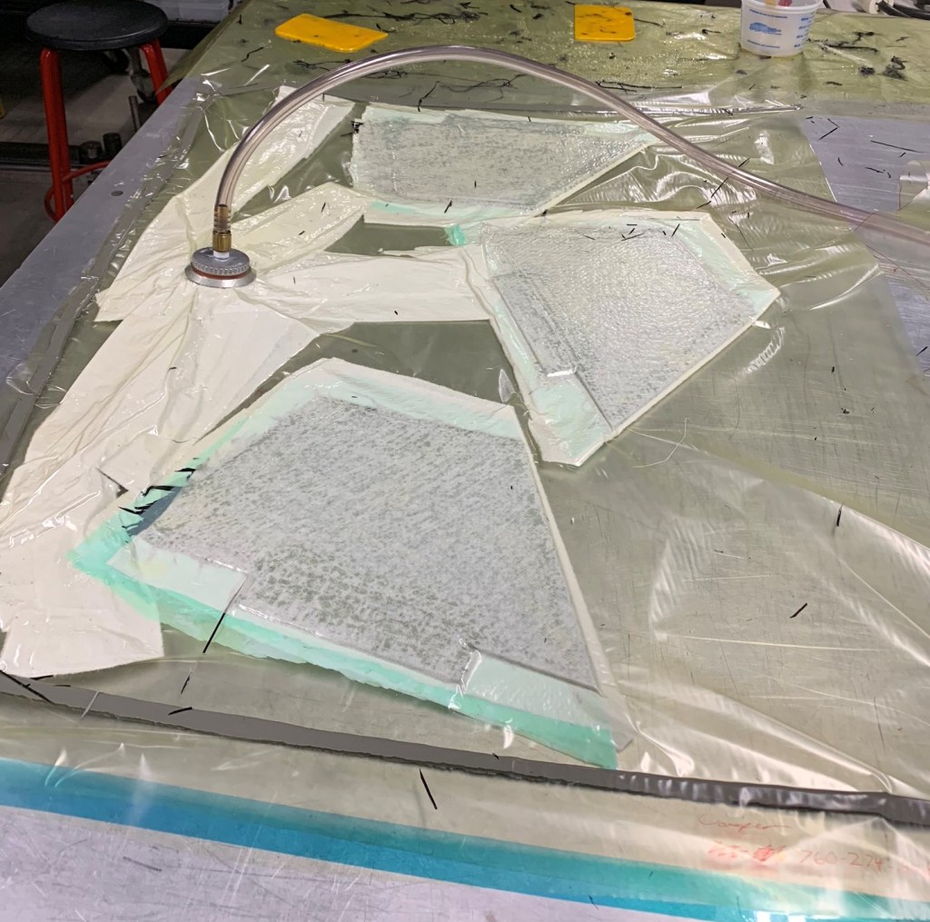

The fins were printed on a FORTUS 250mc with the lowest infill density parameter selected. Because of the infill settings and composite material, analysis was difficult. To overcome the complexities of composite analysis, it was decided that the fins would be modeled as solid ABS structures and analyzed in that manner, the logic being that CF is considerably stronger than ABS. CFD was performed to gain an understanding of flow patterns on symmetric airfoils. Furthermore, the pressure data gathered from the flow study was exported to FEA to determine if the fins would yield. From this analysis, it was found that minimal displacement would occur and that the fins would not yield. AeroFinSim was also employed to determine fin flutter velocity, which was expected to occur at 1977 ft/s. This was over double the max velocity of the rocket, ensuring the fins would not flutter.


Payload
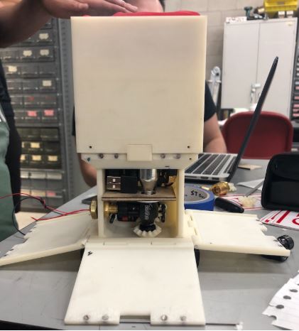
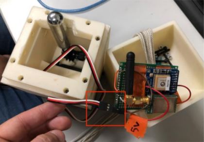
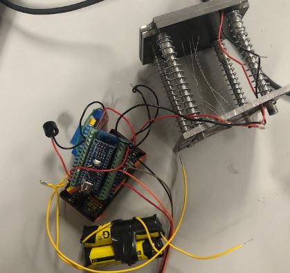
The remainder of the team worked on other aspects of the project including payload and electronics. Our team decided to store a 3U cubesat-styled payload into the upper stage of the rocket. The lower unit of the 3U was a spring-loaded ejection mechanism which was used to push out the upper two units. The upper two units were connected. One unit housed electronics and the parachute. The lower unit had an inflatable habitat controlled by a servo and CO2 canister. The upper units would eject from the rocket around an altitude of 1000 ft, deploy a parachute, and descend down to earth. Upon landing, a motor connected to a bike pump valve would pierce the CO2 canister allowing some gas to inflate the habitat and force open doors on the exterior of the 2U.
Avionics
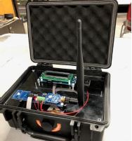
The electrical engineering and computer science majors handled all the electronics for this project. The primary system for the entire rocket was housed in an avionics bay designed to fit in the nosecone. The system incorporated the Missile Works’ RTx/GPS tracking system, RRC3, and a stratologger. A ground station was also developed to assist the recovery team. The payload unit utilized a separate system consisting of an arduino nano, GPS and LoRa radio transmitter, and a sensor board (altimeter, gyroscope, accelerarometer, and magnetometer).


Conclusion
A video of the launch can be seen below. The Loveship reached an altitude of 8200 ft and a max velocity of 814.7 ft/s. Overall, our team placed 26th out of 107 total, and 12th out of 46 teams in our category. We believe substantial altitude loss occured due to non-nominal weather. In addition to this, it appears the rocket trajectory off the launch rail temporarily follows a non-linear path before correcting itself, which may have been caused by a launch lug getting misgrooved on the rail.
Acknowledgements

None of this could have been accomplished without the contributions of all the diligent members of this team. I have provided links to some of their websites/LinkedIn’s should you want to check any of them out as well!
- Jacob Reed (Avionics Lead) https://www.jacobpreed.com/
- Victor Taksheyev (Avionics/Payload) https://victortaksheyev.github.io/portfolio/index.html
- Edgar Salas-Sanchez (Assembly) https://www.linkedin.com/in/esalas-sanchez/
- Brandon Avendaño (Payload Lead) https://www.linkedin.com/in/brandon-avendano-morales-768b7319a/
- Nick Chai (Co-Composites Lead) https://www.linkedin.com/in/nicholas-chai-438577178/
- Mariana Rodriguez (Project Manager) https://www.linkedin.com/in/m-rodriguez-sifuentes/
- Keane Pimentel (Payload) https://www.linkedin.com/in/keanepimentel/
- Cody McDonald (Avionics) https://www.linkedin.com/in/cody-mcdonald-b6a5835a/
Click below to see a recap video of our journey!
Check out some other exciting launches too!

