Project Introduction
In a standard liquid or hybrid rocket engine, thrust can only be throttled by varying the mass flow rate of the propellants which serves as the only means of thrust control. A professor at my undergraduate university was working on a nuclear thermal rocket (NTR) project and was seeking a method to control thrust via the nozzle. For my capstone project, I decided to develop a variable-throat rocket nozzle (VTRN) on a $750 budget. By altering the area of the throat, thrust can be effectively controlled.
Propellant Selection
For this project, we chose to use acrylic and gaseous oxygen to make a hybrid motor. This selection was largely based on low cost and ease of accessbility. Unless your university already has approval, storing more volatile propellants on campus typically involves going through many safety hurdles which can take upwards of a year to complete. The oxygen tank was stored off-campus to avoid such hurdles.
Throat Iris Design
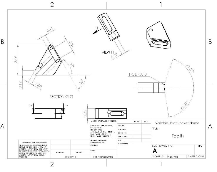
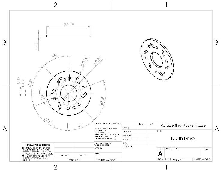
For this project, my teammate Edgar led the design for the iris mechanism which was used to control the throat area. The final design incorporated six teeth which could be spun uniformally inwards, similar to a camera shutter. The teeth were interconnected via a tongue-and-groove mechanism and dowel pins were inserted into the teeth which were connected to a driver plate.

3D printed prototypes were made to test fitment and ease of rotation. Once we confirmed that a functionable design was achieved, Edgar began integrating the mechanism into the nozzle contours. The mechanism evolved to incorporate a gear drive which could be driven from a motor connected outside the nozzle.
Material Selection
Because of the cost constraints, a cheap metal was required. 304 Stainless Steel (SS) was selected as the main material for the nozzle components. Gearing was used inside the nozzle spin the components. Several of these gears were also 304 SS, but some were also made from aluminum.
Theoretical Performance
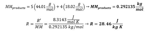
Selecting acrylic as the fuel came with its own challenges. Available data for acrylic is limited, making it difficult to analyze. Due to the unavailability of known combustion products, a simplified reaction was chosen for analysis.
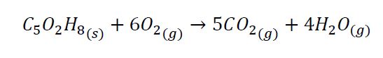
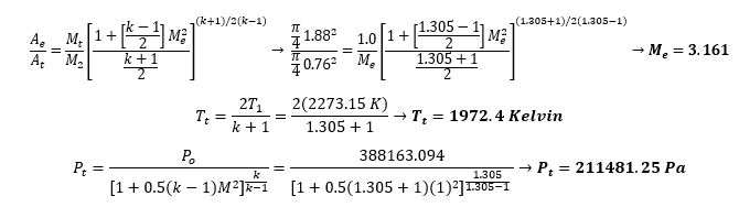
Outlined below are some sample calculations performed.
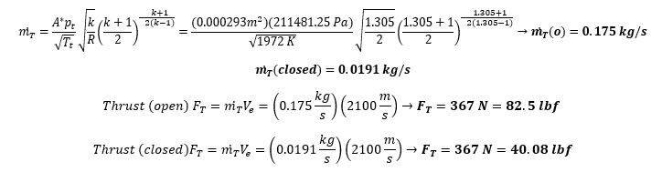
Flow Analysis
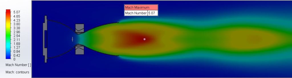
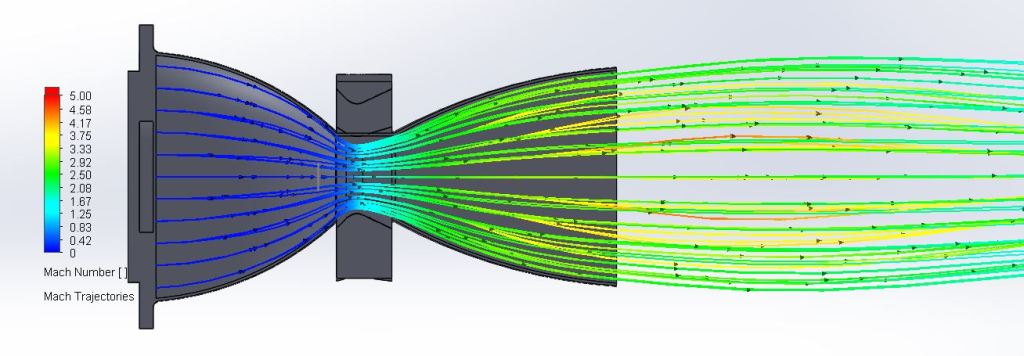
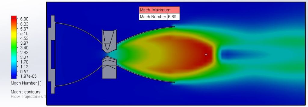
As this was my first propulsion project, my knowledge was very limited. Due to this, I ran CFD in SolidWorks FlowSim to compare values. The results of this analysis are shown below in the slideshow.
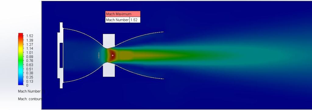
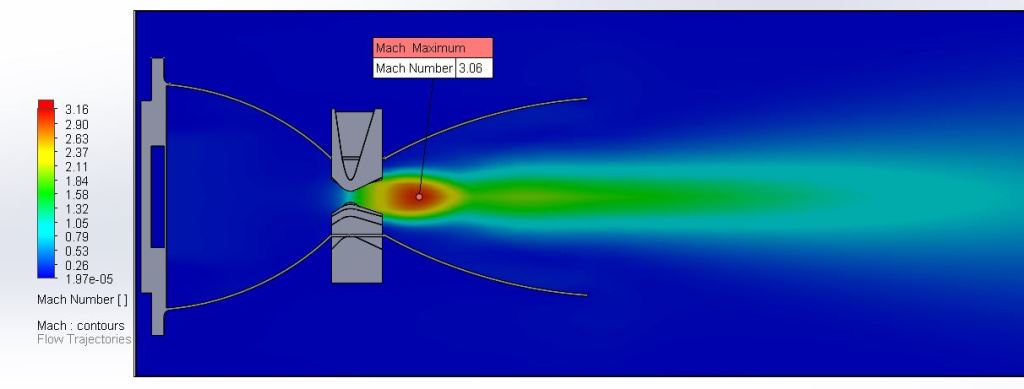
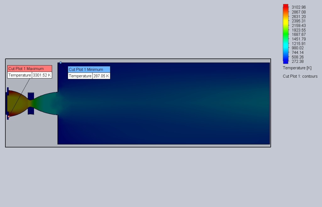
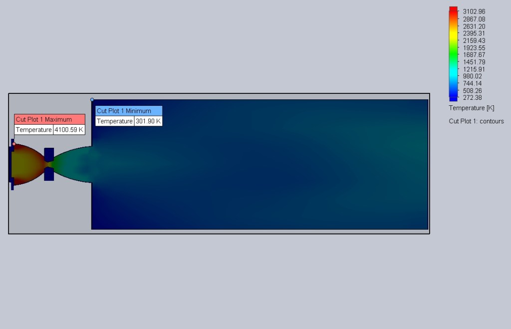
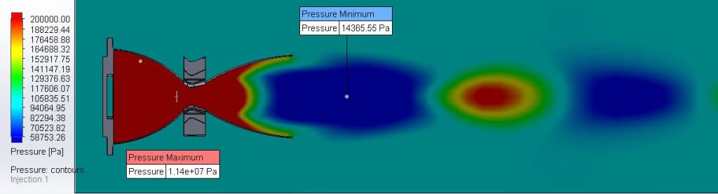
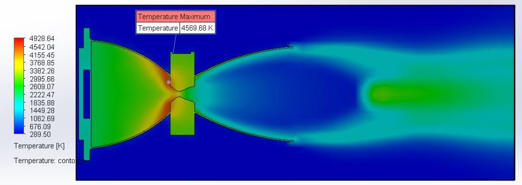
The analysis showed that a variation in outlet Mach number was achieved. The Mach values at the exit had about a 10% difference when compared to the theoretical values. As such, we knew this wasn’t going to be extremely accurate, but it proved the concept. Temperature values at the throat and exit very nearly matched the theoretical values, increasing trust in the analysis, but the pressure was drastically different.
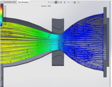
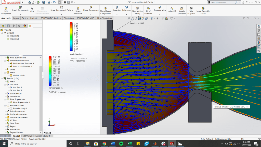
Next, streamlines were investigated to check for backflow. The left image shows the fully open throat scenario, whereas the right shows the minimum reduction in area scenario. From this analysis, it was shown that the design was flawed from the get-go. The max diameter of purchasable acrylic was 2 inches and the grain’s port could not exceed 1.25 inches due to length limitations of the drill bits used. To compensate for these limitations, a ledge for the acrylic to sit on was incorporated, but this caused substantial backflow. The inlet diameter of the nozzle was modified in attempt to fix this backflow error, but the simulation continually failed. With limited time and lack of simulation validation, we regrettably chose to keep this design and proceed to ensure we had a final product to graduate. Future designs (shown at the bottom) would incorporate this fix.
Structural Analysis
The pressure data gathered from the simulation was then imported into SolidWorks FEA. Two different methods were investigated here. In the first, the entire assembly was analyzed. In the second, a split line was drawn across a single tooth and theoretical steady-state temperature and pressures were applied.
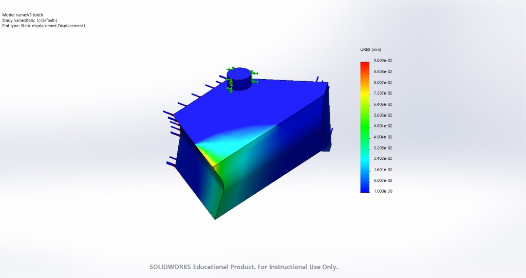
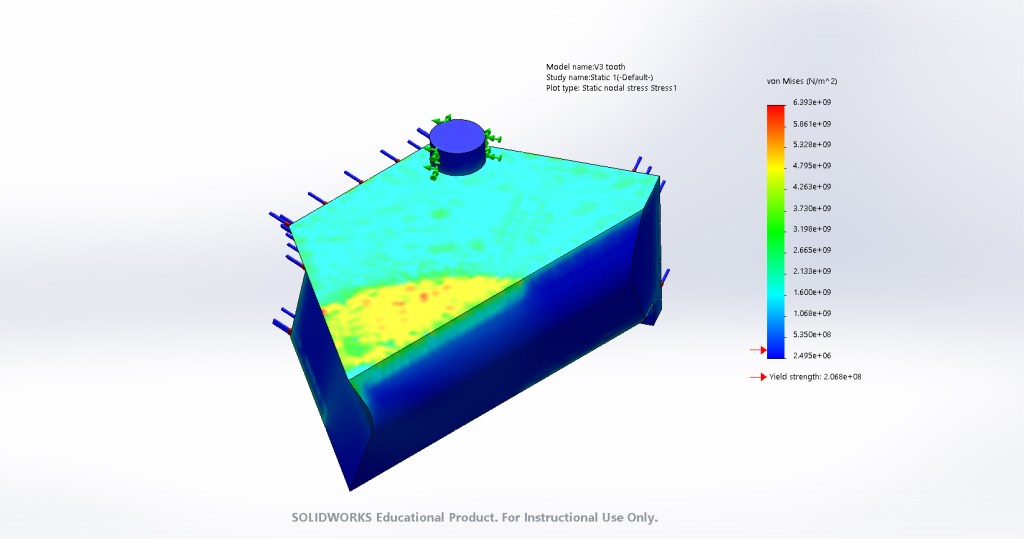
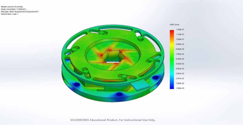
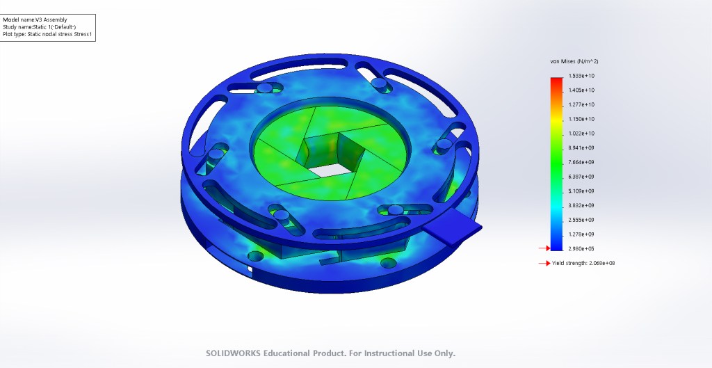
From the analysis, it became apparent that the iris would undergo yielding should a steady-state temperature of 2273 Kelvin be reached. To practically offset this, the motor was run in short burst to ensure steady-state values would not be achieved.
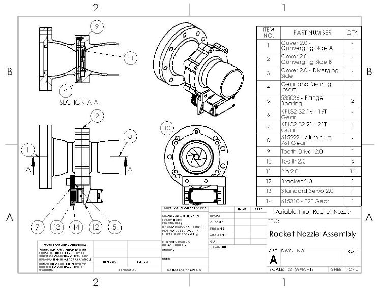
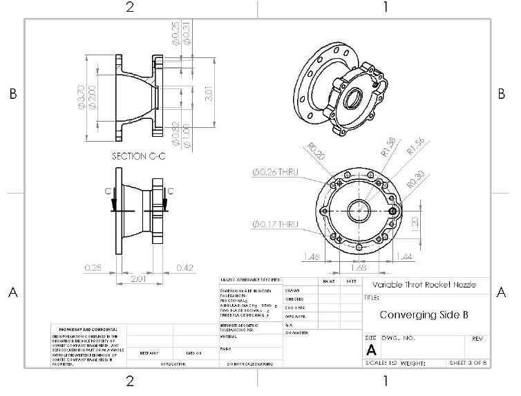
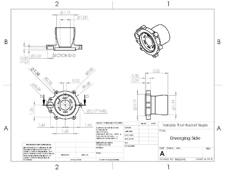
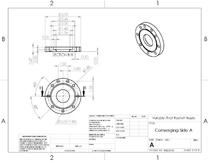
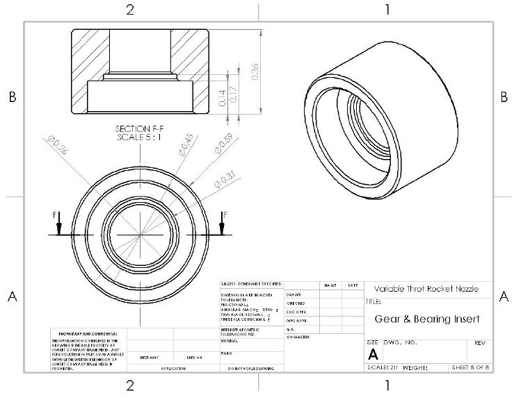
Once the optimal nozzle contours had been determined, the iris design was merged with it. Several o-rings and gaskets were incorporated where possible to prevent combustion gases from leaking. The final drawings can be seen below.
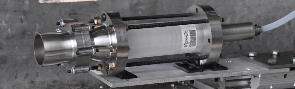
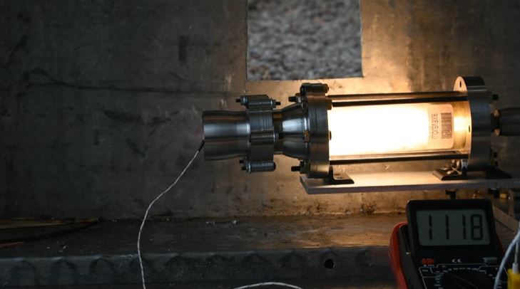
Testing
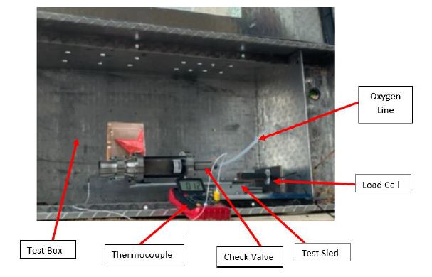
An old test sled for testing small estes motors was modified to fit our needs. An image of the setup can be seen below. An oxygen tank sat a sufficient distance away with a pressure regulator rated for 0 – 120 psi. A steel check valve was connected to the system and acted as the injector for this setup. A disk-type load cell rated for 80 kg was utilized to gather thrust data. A K-type thermocouple was placed at the exit of the nozzle to compare theoretical and computationally determined values.
Results
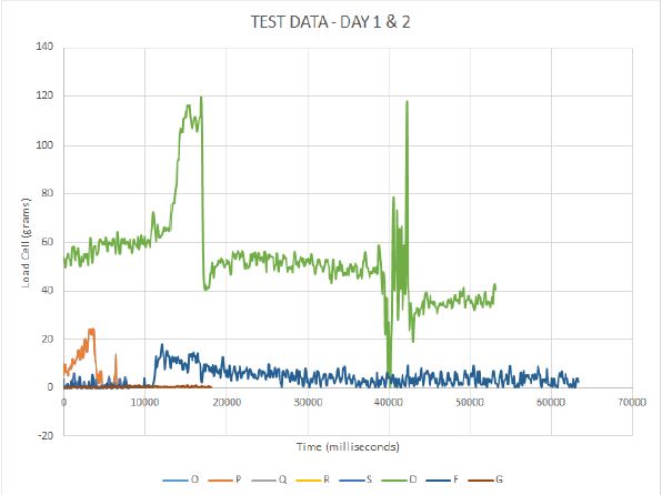
The data gathered was far from ideal, with a max output of 120 grams. We believe the main culprit of poor data to be the load cell. Prior to testing, there were issues with finding the correct calibration factor and zeroing it out. Unfortunately, the nozzle manufacturing was completed during the final week and a new, higher quality load cell could not be ordered on time.
Further issues arose with the motors ability to spin the teeth. The teeth frequently got stuck on eachother and lose the ability to spin. The reason for this is somewhat uncertain, but we believe it is due to stainless on stainless contact creating high frictional forces. To complete our testing, we opted to perform several test with the nozzle fully open and fully closed.

Future Work
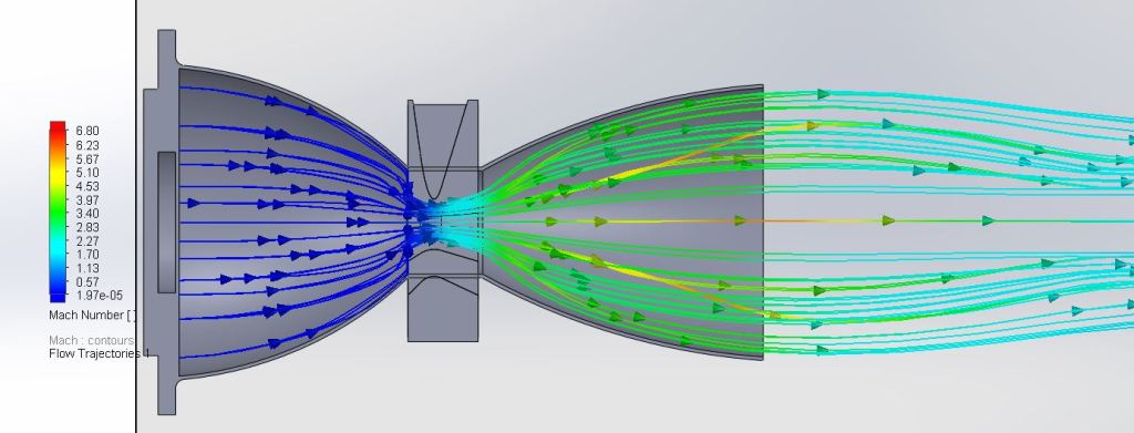
Following the completion of the project, designs were edited to fix errors that occured. One primary error was the backflow in the converging end caused by sudden expansion at the nozzle inlet. Instead of using a 1.25 in inlet, the entire inlet section was used which produced a considerably different result. In the simulation, a more standard flow field was achieved, even showing the evolution of mach diamonds.


Acknowledgements


Edgar Salas-Sanchez: https://www.linkedin.com/in/esalas-sanchez/
Mariana Rodriguez: https://www.linkedin.com/in/m-rodriguez-sifuentes/
Terry Kell (machinist): https://www.unlv.edu/people/terry-kell
Final Report PDF
